AP Physics B: Formula Sheet
|
Table of Contents
|
Kinematics
Variables
- $x, y$ represent displacement, or the distance away from the original point, in metres (vector)
- $a$ represents acceleration, in $m/s^2$ (vector)
- $g$ represents acceleration due to gravity, $g \approx 9.8 m/s^2$ (vector)
- $v_0$ represents initial/original velocity, in $m/s$ (vector)
- $v_f$ represents final velocity, in $m/s$ (vector)
- $t$ represents elapsed time, in seconds (scalar)
Equations
- $v_f = v_0 + at$
- $x = v_0t + \frac{1}{2}at^2$
- $x = \frac{1}{2}(v_0+v_f)t$
- $v_f^2 = v_0^2 + 2ax$
Notes
- The acronym "vvtax" can help you to remember the variables that need to be found. List the ones you have and use the pertinent formula to determine the desired missing variable.
- If the problem involves two dimensions, solve for the $x$ components and the $y$ components separately, and recombine these values at the end, using trigonometry or the Pythagorean Theorem. The same equations apply for both directions.
- Decide which direction is $+$ and which is $-$, and apply these signs to vectors accordingly.
- If the equation has a squared value, you can use the quadratic equation to solve it.
- $g$ is often negative, as it is used in freefall equations to indicate the pull of gravity in the down direction
- Freefall refers to an object that is falling with only the force of gravity acting on it. That is, air resistance is ignored and it is not touching any surfaces. If it is close to the surface of the Earth, the acceleration in the $y$ direction, $a_y$, will be $-g$.
- A projectile is an object that has been shot or thrown such that it is given an initial velocity and then enters freefall. These equations follow the same principle as freefall. Often, the velocity needs to be broken into $$x$$ and $y$ components based on a given angle.
- In the freefall and projectile equations, the position of the object graphed against time will form the shape of a parabola. At symmetric points on the parabola, the velocities will be the same, but in opposite directions. Most importantly, start and end times are the same, but opposite, and the velocity at the top of the curve, its peak height, is $$0 m/s$$
Forces and Newton's Laws of Motion
Variables
- $F$ or $\overrightarrow{F}$ represents force, measured in Newtons (N) (vector)
- $m$ represents mass, measured in kilograms (kg) (scalar)
- $G$ represents the universal gravitational constant: $G \approx 6.673e-11 \frac{N \cdot m^2}{kg^2}$ (scalar)
- $r$ represents the distance between the centres of two objects when measuring gravitational acceleration (scalar)
- $W$ or $F_g$ is the weight (or force due to gravity) of an object, measured in Newtons (vector)
- $F_N$ represents the normal force, the force that pushes against an object when it is in contact with a surface, measured in Newtons (vector)
- $f_s^{MAX}$ represents the maximum static friction force, measured in Newtons (vector)
- $f_k$ represents the kinetic friction force, measured in Newtons (vector)
- $\mu$ represents the friction constant, $\mu_s$ for static and $\mu_k$ for kinetic; no units (scalar)
- $T$ represents a tension force, measured in Newtons (vector)
Equations
- $\Sigma F = ma$ (Newton's Second Law, the net force is mass times acceleration)
- $\Sigma F_x = ma_x$
- $\Sigma F_y = ma_y$
- $F_g = G\dfrac{m_1 m_2}{r^2}$
- $F_g = G\dfrac{m_E m}{r^2}$ and $G\dfrac{m_E}{r^2} = g$ near the surface, so:
- $F_g = mg$, near the surface of the earth
- $f_s^{MAX} = \mu_s F_N$
- $f_k = \mu_k F_N$
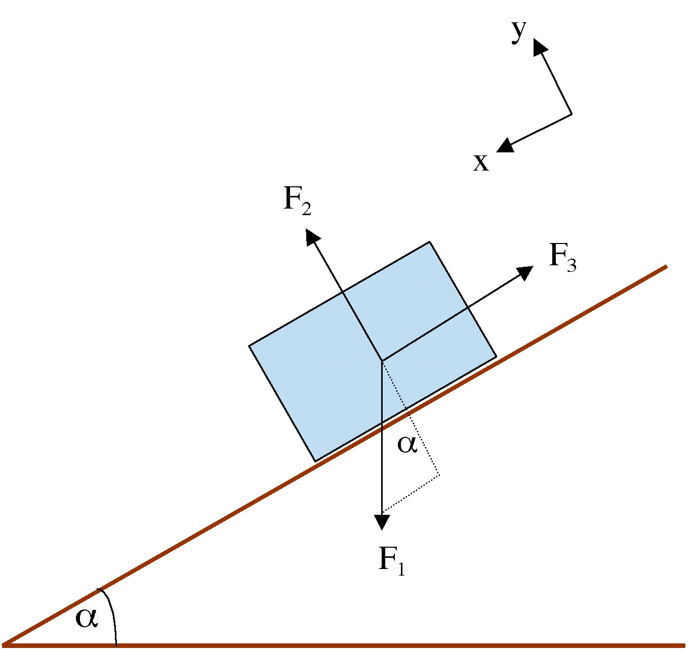
- $\mu_s = tan \theta$ when the object just begins to slide on a tilted surface
Notes
- Newton's First Law states that an object at rest or in motion remains that way unless a net force acts on it
- Inertia is not a force; so when going around curves, etc., the motion one feels is not a force
- Newton's Third Law states that for every force, there is an equal and opposite reaction force
- Free Body Diagrams can be used to help determine the forces acting on an object and their direction. This helps one to visualise which forces act in the $x$ and $y$ directions, and which cancel each other out.

- Apparent weight is the normal force from a scale. If the scale and the object on it are accelerating, the apparent weight differs from the actual weight: $W_{apparent} = mg + ma$
- The normal force is perpendicular to the surface on which the object rests. If the surface is parallel to the Earth, normal force and weight are in opposite directions. If the surface is on an angle, the normal force is perpendicular to the surface, not perpendicular to the Earth - so it's not in the same direction as the weight.
- Friction is parallel to the direction of motion, in the opposite direction
- Static friction is the force opposite to and equal to a force on a stationary object. Once the maximum static friction force is surpassed by the applied force, the object moves, and friction is now kinetic friction. The equation for static friction only gives the maximum; if the applied force is not equal to the maximum, then static friction is less than the maximum.
- When an object is in equilibrium, it has zero acceleration (constant velocity or at rest). Thus: $\Sigma F_y = 0$ and $\Sigma F_x = 0$
- To solve and equilibrium problem:
- Select the object or system of interest.
- Draw a free body diagram.
- Choose an x-y axis and break all forces into components along these axes.
- Use $\Sigma F_y = 0$ and $\Sigma F_x = 0$ to solve for the desired unknowns.
- Use the same strategy when the object is not in equilibrium; however: $\Sigma F = ma$, broken in to components if necessary
Uniform Circular Motion
Variables
- $T$ represents the period, or time for one revolution, measured in seconds (scalar)
- $v$ represents the speed, measured in metres/second (scalar)
- $r$ represents the radius of the circle, measured in metres (scalar)
- $a_c$ represents the centripetal acceleration, measured in metres/second/second (vector)
- $F_c$ represents the centripetal force, measured in Newtons (vector)
Equations
- $v = \dfrac{2\pi r}{T}$
- $a_c = \dfrac{v^2}{r} = \dfrac{4\pi^2r}{T^2}$
- $F_c = \dfrac{mv^2}{r}$
- $v_{max} = \sqrt{r\mu_s g}$ on a banked curve, because static friction is the centripetal force
- $tan \theta = \dfrac{v_{max}^2}{rg}$ on a banked curve, without using friction (component of normal force provides centripetal force)
- $v = \sqrt{\dfrac{GM_E}{r}}$ for satellites in circular orbits (gravity is centripetal force)
- $v_{min} = \sqrt{rg}$ for a rider to stay on a vertical circular track at the top (on inside or outside)
Notes
- Uniform circular motion is the motion of an object travelling at constant speed on a circular path.
- Velocity is not constant, as the object is always changing direction.
- Centripetal acceleration always points towards the centre of the circle.
- The centripetal force is the force that causes the acceleration. It's not a new force, rather, it can be gravity, or tension, or friction, etc.
- $v = \dfrac{2\pi r}{T}$ and $v = \sqrt{\dfrac{GM_E}{r}}$, so $T_{satellite} = \dfrac{2\pi r^{3/2}}{\sqrt{GM_E}}$
- For vertical circular motion, centripetal force can be calculated at four points:
- Bottom: $F_N - mg$
- Top: $F_N + mg$
- Left and right, parallel to ground: $F_N$
Work, Energy, and Power
Variables
- $W$ represents work, measured in Joules (scalar)
- $s$ represents displacement, measured in metres (scalar)
- $\theta$ represents the angle between the force and the displacement, measured in degrees (scalar)
- $PE$ represents potential energy, measured in Joules (scalar)
- $KE$ represents kinetic energy, measured in Joules (scalar)
- $\Delta$ (delta) represents a change in a quantity
- $PE_g$ represents gravitational potential energy, measured in Joules (scalar)
- $W_{nc}$ represents work done by non-conservative forces, measured in Joules (scalar)
- $E$ represents the total energy of an object, measured in Joules (scalar)
- $P$ represents Power, measured in watts (W) (scalar)
- $t$ represents time, measured in seconds (scalar)
Equations
- $W = (Fcos\theta)s$
- $PE_g = mgh$
- $KE = \frac{1}{2}mv^2$
- $W = \Delta KE = KE_f - KE_0 = \frac{1}{2}mv_f^2 - \frac{1}{2}mv_0^2$
- $E = KE + PE$
- $W_{nc} = E_f - E_0$
- $\overline{P} = \dfrac{W}{t} = \dfrac{Fs}{t} = F\overline{v}$
Notes
- No work is done if there is no displacement.
- If the force has a component in the direction of the displacement, the work is positive.
- If the force opposes the motion, the work is negative.
- When the force is parallel to the displacement, $cos\theta = cos0 = 1$; often, it's easier to break the force into components and use only the appropriate component.
- On a force versus distance graph, the area under the curve is $F\cdot x$, which is work.
- Mechanical energy is energy due to motion (kinetic) or position (potential).
- Any object which possesses mechanical energy is able to do work.
- A force is conservative when the work it does on an object is independent of the path the object takes; it does no net work on an object moving around a closed path; examples include gravity and springs.
- Non-conservative forces, such as friction and propulsion, perform more work if the object's path is longer - the net work done on a closed path is not zero.
- The Principle of Conservation of Mechanical Energy states that the total mechanical energy of an object, $E$, remains constant as the object moves, provided that $W_{nc} = 0$, that is, $E_f = E_0$.
- The sum of the the potential and kinetic energies remains constant - the two types may be converted into each other.
- Problem solving strategy:
- Identify the external conservative and non-conservative forces that act on the object. $W_{nc}$ must equal zero.
- Choose a location where gravitational potential energy is taken to be zero.
- Use $E_f = E_0 \Longrightarrow KE_f + PE_f = KE_0 + PE_0$
- Power is the rate at which work is done, so the average power is work divided by time.
Impulse and Momentum
Variables
- $p$ represents the momentum of an object, measured in kilogram-metres per second (scalar)
- $P$ represents the total momentum of a system
- $J$ represents impulse, measured in Newton-seconds (vector)
Equations
- $p = mv$
- $J = \overline{F}\Delta t$ (average force times time)
- $J = \Delta p = p_f - p_0$
Notes
- Momentum is proportional to an object's mass and velocity.
- Impulse is the average force times the time during which the force acts
- The Impulse-Momentum Theorem states that impulse is the change in momentum; this is useful because changes in velocity are easier to measure than are forces and time
- Conservation of Linear Momentum states that momentum is conserved when the sum of the external forces on a system is zero (an isolated system has no net external force). This implies that $P_0 = P_f$.
- When two objects collide without friction, etc. (the system is isolated), linear momentum is conserved. However, some kinetic energy is usually lost, in the form of heat, dents, etc.
- Types of collisions:
- Elastic
- $KE_0 = KE_f$ and $P_f = P_0$
- large changes in velocity, momentum; large impulse, force
- $v_{1o} - v_{2o} = -(v_{1f} - v_{2f})$
- this equation can be solved for one velocity in terms of the other, then plugged into $mv$ for $P_f = P_0$.
- Inelastic
- some energy is lost, but momentum is still conserved
- if the objects stick together, the collision is completely inelastic
- $P_0 = P_f \Longrightarrow m_1v_{1o} + m_2v_{2o} = (m_1+m_2)v_f$
- Elastic
- When collisions occur at an angle, momentum is conserved in both the $x$ and $y$ directions; break into components and solve
Rotational Motion
Variables
- $\theta$ represents the angle rotated through, from initial ($\theta_0$) to final ($\theta$), measured in radians (scalar)
- $\omega$ represents angular velocity, measured in radians/s (vector)
- $t$ represents time, measured in seconds (scalar)
- $\alpha$ represents angular acceleration, measured in radians/s/s (vector)
- $I$ represents the moment of inertia, measured in $kg \cdot m^2$ (scalar)
- $L$ represents angular momentum, measured in $N\cdot m\cdot s$ or $J\cdot s$
Equations
- $\overline{\omega} = \dfrac{\Delta \theta}{\Delta t}$
- $\overline{\alpha} = \dfrac{\Delta \omega}{\Delta t}$
- $I = mr^2$ for a particle
- $L = I\omega$
- $L = mvr$ for point particles
Notes
- The rotational motion terms are the equivalent to the same linear motion ideas. The kinematics equations can also be applied.
- For larger objects, such as cylinders, rings, etc., the moment of inertia is based on a multiple of $mr^2$.
- The greater the mass and the farther away is it from the axis, the greater the resistance to change in rotational motion.
- Angular momentum is conserved, just as linear momentum is conserved, when the net external torque is zero.
- Spinning objects have a momentum that helps them resist external torques.
Torque
Variables
- $\tau$ represents torque, measured in Newton-metres (vector)
- $\ell$ represents the lever arm, measured in metres (scalar)
- $x_{cg}$ represents the centre of gravity, measured in metres (scalar)
Equations
- $\tau = \ell F$
- $x_{cg} = \dfrac{F_{g1}x_1 + F_{g2}x_2 ...}{F_{g1}+F_{g2}_2 ...} = \dfrac{\Sigma \tau}{\Sigma F_g}$
- $\tau = mr^2\alpha$ on an object in circular motion
Notes
- Torque is what causes an object to rotate - a net force causes linear acceleration, whereas a net torque causes angular acceleration.
- The lever arm is the line that is perpendicular to the "line of action" (a line drawn through the force) and goes through the axis of rotation; if it goes through the line of action, $\ell = 0$, so there's no torque.

- Torque is positive if turning is counterclockwise, negative if clockwise (by convention).
- Equilibrium: no net forces or torque: $\Sigma F = 0$ and $\Sigma \tau = 0$.
- To solve problems, draw a free body diagram and the sums of the forces in the x and y directions. Then, choose a convenient axis of rotation to cancel out forces whose values are not known. When only one unknown remains, solve for it using either a sum of forces equation of a sum of torques equation.
- When an object is on a hinge, pin, joint (anatomy), or other connection, there is a force from that object. Its magnitude and direction are usually not known, so solve for each of its components, and use the Pythagorean Theorem to turn those two values into one force.

Table: Rotational vs. Linear variables
| Variable | Linear | Rotational |
|---|---|---|
| Inertia | $m$ | $I = mr^2$ |
| Velocity | $v$ | $\omega$ |
| Acceleration | $a$ | $\alpha$ |
| Displacement | $x$ or $s$ | $\theta$ |
| Force | $F = ma$ | $\tau = I\alpha$ |
| Momentum | $p = mv$ | $L = I\omega$ |
- $F=ma$ becomes $\tau = mr^2\alpha$ for a particle in angular/circular movement.
- $F\Delta t = \Delta p$ becomes $\Sigma \tau \Delta t = \Delta L$
- $W = Fs$ becomes $W_R = \tau \theta$
- $KE = \frac{1}{2}mv^2$ becomes $KE_{rotational} = \frac{1}{2}I\omega^2$; rotating objects can have both translational and rotational kinetic energy: $KE_{total} = \frac{1}{2} mv^2 + \frac{1}{2} I \omega^2$
Hooke's Law and Simple Harmonic Motion
Variables
- $k$ represents the spring constant, measured in Newtons/metre (scalar)
- $x$ represents the displacement from an unstretched rest position, measured in metres (scalar)
- $T_s$ represents the period of a spring in simple harmonic motion, measured in seconds (scalar)
- $W_{elastic}$ represents work done by a spring, measured in Joules (scalar)
- $PE_{elastic}$ represents the elastic potential energy, measured in Joules (scalar)
- $T_p$ represents the period of a pendulum, measured in seconds (scalar)
- $L$ represents the length of the pendulum, measured in metres (scalar)
Equations
- $F_{spring} = kx$ for ideal springs; this is Hooke's Law
- $F_{restoring} = -kx$
- $T_s = 2\pi \sqrt{\dfrac{m}{k}}$
- $PE_{elastic} = \frac{1}{2}kx^2$
- $W_{elastic} = PE_{elastic}_0 - PE_{elastic}_f$
- $T_p = 2\pi \sqrt{\dfrac{L}{g}}$
Notes
- Periodic motion occurs when an objects vibrates back and forth over the same path, with each cycle taking a fixed amount of time.
- Determining the spring constant can often be done by measuring displacement when using a known weight as the force, then $k=F/x$.
- If a spring is cut in half, its spring constant doubles.
- Simple harmonic motion (SHM):
- sinusoidal
- displacement measured from equilibrium
- amplitude is the maximum displacement
- cycle is full to-and-fro motion
- period is time for one cycle
- frequency is cycles per second
Table: Displacement
| x | Max | 0 |
|---|---|---|
| $a$ | max | 0 |
| $v$ | 0 | max |
| $KE$ | 0 | max |
| $PE_{el}$ | max | 0 |
- Energy in SHM
- Objects in vertical SHM have gravitational potential energy
- At $x=0$, there is no elastic potential energy
- At all other displacements, the object has some elastic potential energy
- At the maximum displacement, there is no kinetic energy; usually, this means the object has only elastic potential
- Total mechanical energy at this point is: $E=\frac{1}{2}mv^2+\frac{1}{2}I\omega^2+mgh+\frac{1}{2}kx^2$
- The period of a pendulum is independent of the amplitude and the mass.
Fluids
Variables
- $\rho$ represents density, measured in $kg/m^3$ (scalar)
- $V$ represents volume, measured in cubic metres (scalar)
- $m$ represents mass, measured in kilograms (scalar)
- $P$ represents pressure, measured in Pascals (scalar)
- $F$ represents force, measured in Newtons (vector)
- $A$ represents area, measured in square metres (scalar)
- $P_{atm}$ represents the pressure of the atmosphere at sea level: $P_{atm} \approx 1.013 \times 10^5 Pa$ (scalar)
- $F_B$ represents the buoyant force on an object submerged in a fluid, measured in Newtons (vector)
- $v$ represents velocity, measured in metres per second (vector)
- $Q$ represents volume flow rate, measured in $m^3/s$ (scalar)
- $y$ represents vertical distance from an arbitrary point of zero potential energy, measured in metres (scalar)
Equations
- $\rho = \dfrac{m}{V}$
- $P=\dfrac{F}{A}$
- $P_1 + \rho gh = P_2$ in static, incompressible, fluids
- $F_B = m_{fluid}g$
- $m = \rho V$
- $\dfrac{\rho_{object}}{\rho_{fluid}} = \dfrac{h_{submerged}}{h_{total}} = \dfrac{V_{fluid}}{V_{object}}$
- $Q=Av$
- $P + \frac{1}{2}\rho v^2 + \rho gy =$ a constant at every point (Bernoulli)
Notes
- Specific gravity is $\dfrac{\rho_{substance}}{\rho_{water}} = \dfrac{\rho_{substance}}{1000}$; it has no units, being a ratio.
- In static fluids, pressure is the same and perpendicular surrounding an imaginary cube placed in the fluid. Forces, therefore, are also perpendicular to the surface; only the magnitude is used in the equation for pressure, as pressure is not a vector - the force is always perpendicular.
- Pressure in a static fluid does not depend on shape or horizontal distance.
- Gauge pressure is pressure relative to a "standard" pressure, usually atmospheric.
- Pascal's Principle: any change in pressure in a completely enclosed fluid is transmitted unchanged to all parts of the fluid and enclosing walls.
- $P_1 = P_2$
- $\dfrac{F_1}{A_1} = \dfrac{F_2}{A_2}$
- $V_1 = V_2 \Longrightarrow \dfrac{A_1}{A_2} = \dfrac{\Delta x_2}{\Delta x_1}$
- $\dfrac{F_1}{F_2} = \dfrac{\Delta x_2}{\Delta x_1}$
- Work is the same, so: $F_1 \Delta x_1 = F_2 \Delta x_2$
- Add $\rho gh$ if necessary, given height differences in pistons, to compensate for the weight of the fluid.
- Archimedes' Principle: the buoyant force on an object submerged in a fluid equals the weight of the displaced fluid.
- If the object is floating, $F_g = F_B$
- Often, mass needs to be replaced by $\rho V$
- Even if the object sinks, there is still a buoyant force
- If the density of the object is greater than the density of the fluid, it sinks

- For an object weighed in air and in fluid, the buoyant force is the difference between the weights.
- Fluid Flow:
- incompressible (most liquids)
- compressible (most gases)
- viscous (high internal friction in fluid)
- non-viscous (zero friction ideal)
- streamline flow (all particles follow the same path)
- Ideal Fluid
- non-viscous
- incompressible
- steady motion
- no turbulence
- Equation of Continuity: Volume flow rate is constant in a closed environment if no fluid is added or removed.
- Bernoulli's Equation relates pressure to velocity and elevation; assumes an ideal fluid.
- Toricelli's Theorem is derived from Bernoulli; for a large tank with a small hole, $v = \sqrt{2gh}$. This is because the pressures are equal and the velocity at the top is nearly zero. [Note: this equation is not valid for the AP exam, instead derive it from Bernoulli]

Temperature and Heat
Variables
- $T$ represents temperature, measured in Kelvins (scalar)
- $L$ represents length or thickness, measured in metres (scalar)
- $\alpha$ represents the coefficient of thermal expansion, measured in inverse Kelvins (scalar)
- $A$ represents area, measured in square metres (scalar)
Equations
- $T_{Celsius} = T_{Kelvin} - 273.15 = \frac{5}{9}(T_{Fahrenheit}-32)$
- $\Delta L = \alpha L_0 \Delta T$
- $\Delta A = \alpha_A A_0 \Delta T$
- $\Delta V = \alpha_V V_0 \Delta T$
- $\alpha_A \approx 2\alpha$ for solids; varies for liquids
- $\alpha_V \approx 3\alpha$ for solids; varies for liquids
Notes
- "Thermal physics" is the study of temperature, heat, and their effects on matter. It deals with energy transfers and physical and chemical transformations of matter.
- Heat is the process by which energy is exchanged between objects. It moves from hotter temperature to cooler temperature.
- Objects are in thermal contact if energy can be exchanged between them.
- Thermal equilibrium exists when two objects in thermal contact cease to exchange energy.
- Zeroth Law of Thermodynamics: If A and B are in thermal equilibrium with C, then A and B are in thermal equilibrium with each other; they are at the same temperature.
- Temperature is the indicator of thermal equilibrium - no net heat flow occurs between two systems at the same temperature.
- In a mercury thermometer, thermal expansion causes the mercury level to rise; the mercury expands more than the glass does.
- All gases go to absolute zero (0 K = -273 C) at zero pressure.
- Thermal expansion occurs because molecules vibrate with a higher amplitude at higher temperatures.
- Holes undergo thermal expansion in the same way as the surrounding material.
- Water contracts as T goes from 0 to 4 Celsius; outside of this range, it exhibits normal expansion. Its maximum density is 1000 $kg/m^3$ at 4 C.
Heat Transfer
Variables
- $Q$ represents heat, measured in Joules (scalar)
- $t$ represents time, measured in seconds (scalar)
- $k$ represents the thermal conductivity of a material, measured in $W / m \cdot K$ (scalar)
- $A$ represents the cross-sectional area, measured in square metres (scalar)
- $L$ represents the thickness of a slab or the length of a rod, measured in metres (scalar)
- $R$ is a method of rating substances for home insulation
- $e$ represents the emissivity, which varies from 0 to 1 for different substances; no units (scalar)
- $\sigma$ is the Stefan-Boltzman constant, $\approx 5.6696 \times 10^{-8} W/m^2\cdot K^4$
Equations
- $\dfrac{Q}{\Delta t} = kA\dfrac{T_h-T_c}{L}$ for conduction
- $P = \dfrac{Q}{\Delta t}$
- $R=\dfrac{L}{k}$
- $\dfrac{Q}{\Delta t} = e \sigma T^4 A$ for radiation; this is the Stefan-Boltzman Law
Notes
- Convection is energy transferred by the movement of a fluid. A classic example is a radiator heating a room.
- Conduction is the transfer of energy through contact of a material. It can be viewed on an atomic scale, involving collisions between particles.
- Metals are generally good conductors, as they contain large numbers of electrons that are free to move.
- Radiation does not require physical contact. All objects radiate energy continuously in the form of electromagnetic waves due to thermal vibrations of their molecules.
- Emissivity, $e$ or $\epsilon$ is a constant for a substance that expresses its rate of absorption and radiation. An ideal absorber is also an ideal radiator, and $e=1$; these objects are known as black bodies. An ideal reflector absorbs no energy, $e=0$. Black or dark objects tend to have higher emissivities.
Ideal Gas Law and Kinetic Theory
Variables
- $n$ represents the number of moles of a substance (scalar)
- $N_A$ represents Avogadro's Number, the number of particles in one mole; $N_A \approx 6.02 \times 10^{23}$ (scalar)
- $N$ represents the number of particles in a sample (scalar)
- $P$ represents pressure, measured in Pascals (scalar)
- $V$ represents volume, measured in cubic metres (scalar)
- $R$ represents the universal gas constant; $R \approx 8.31 J/mol \cdot K$
- $T$ represents temperature, measured in Kelvins (scalar)
- $k$ represents Boltzman's constant
- $\overline{KE}$ represents the average kinetic energy of particles in a gas, measured in Joules (scalar)
- $U$ represents the internal energy of a monatomic ideal gas, measured in Joules (scalar)
Equations
- $n=N/N_A$
- $PV = nRT$ (Ideal Gas Law)
- $k = \dfrac{R}{N_A} \approx 1.38 \times 10^{-23} J/K$
- $PV = NkT$
- $\overline{KE} = \frac{2}{3}kT = \frac{1}{2}mv_{rms}^2$
- $U = \frac{3}{2}nRT$
- $\Delta U = \frac{3}{2}nr \Delta T$
Notes
- Boyle's Law states that pressure varies indirectly with volume if temperature and number of molecules are kept constant.
- Charles' Law states that volume varies directly with temperature if pressure and number of molecules are kept constant.
- These two laws can be derived from the Ideal Gas Law.
- Maxwell calculated the speed distribution for particles in a gas; this data is used as part of the kinetic theory of gases.
- "rms" refers to the root-mean-square average of speeds.
- At a given temperature, lighter molecules move faster, on average, than heavier ones.
Thermodynamics
Variables
- $U$ represents the internal energy of a system, measured in Joules (scalar)
- $Q$ represents heat, measured in Joules (scalar)
- $W$ represents work, measured in Joules (scalar)
- $e$ represents efficiency of a heat engine, measured in a percentage (scalar)
- $Q_h$ represents the heat from the hot reservoir of a heat engine, measured in Joules (scalar)
- $Q_c$ represents the heat from the cold reservoir of a heat engine, measured in Joules (scalar)
- $T_h$ represents the temperature of the hot reservoir of a heat engine, measured in Kelvins (scalar)
- $T_c$ represents the temperature of the cold reservoir of a heat engine, measured in Kelvins (scalar)
- $S$ represents entropy, measured in Joules per Kelvin (scalar)
Equations
- $\Delta U = U_f - U_i = Q+W$
- $e = \dfrac{|W|}{|Q_h|} = 1-\dfrac{|Q_c|}{|Q_h|}$
- $e = 1 - \dfrac{T_c}{T_h}$ for a Carnot engine
- $\Delta S = \dfrac{|Q|}{T}$ for a thermal process
Notes
- Heat and work often occur together; thermodynamics covers the basic laws that both heat and work obey.
- The "system" is the collection of objects being studied. The "surroundings" are everything else in the environment. The system and the surroundings are separated by some type of wall.
- Diathermal walls permit heal flow; adiabatic walls permit no heat flow.
- The "state" of a system is defined by the values for pressure, temperature, volume, and mass. A "function of state" is one that relies on these variables.
- Zeroth Law of Thermodynamics: two systems individually in thermal equilibrium with a third system are in equilibrium with each other.
- First Law of Thermodynamics: the internal energy of a system changes due to heat and work: $\Delta U = Q + W$
- There are two ways in which energy can be transferred, causing the change in U: by doing work, which requires a macroscopic displacement of an object; by heat, which occurs through random molecular collisions.
Table: Sign Conventions
| + | - | |
|---|---|---|
| $Q$ | heat entered system; "heat-in" | heat left system; "heat-out" |
| $W$ | work done on system; "work-in" | work done by system; "work-out" |
| $\Delta U$ | temperature increases | temperature decreases |
- The change in internal energy depends only on change in temperature, not on the method used to arrive at that state. Thus, it can be called a function of state.
- Heat and work are not functions of state; they differ according to the process used.
- Thermal Processes
- These four common thermal process are assumed to be quasi-static, that is, the process occurs slowly, so that a uniform pressure and temperature exist throughout the system.
- In each one, one of pressure, volume, or temperature are kept constant; or, there is no heat transfer.
- Isochoric is also referred to as isovolumetric.
- An adiabatic reaction may be one in which the reaction occured too quickly for a heat transfer to take place, such as in a car engine.
Table: Thermal Processes
| Process | Constant | $\Delta U$ | $Q$ | $W$ |
|---|---|---|---|---|
| Isobaric | Pressure | $\frac{3}{2}nR\Delta T$ | $\Delta U - W$ | $-P\Delta V$ |
| Isochoric | Volume | $\frac{3}{2}nR\Delta T$ | $\Delta U$ | 0 |
| Isothermal | Temperature | 0 | $-W$ | $-nRT\ln{\frac{V_f}{V_i}}$ |
| Adiabatic | Heat | $\frac{3}{2}nR\Delta T$ | 0 | $\Delta U$ |
- Pressure - Volume Diagrams
- Thermal processes are represented on a pressure-volume graph when pressure and volume are known for each step of the process. The diagram shows changes in pressure and volume as the change took place.
- The curve on the diagram is the path taken between the initial and final states.
- The work done depends on the path; it is the area under the curve.
- Arrows show the direction in which the process takes place. If the arrows point to larger volumes, the work is negative (the gas expanded). If the arrows point to smaller volumes, the work is positive (the gas compressed).
- If the graph shows a cycle, net work is the area enclosed by the curves.
- If the process ends at the same location as it started at, $\Delta T = 0$ so $\Delta U =0$ and $W = -Q$
Table: P-V Diagrams for Thermal Processes
| Process | Diagram | Notes |
|---|---|---|
| Isobaric |  |
The work is the area under the curve, simply length times width, or $P\Delta V$ |
| Isochoric |  |
There is no work, as there is no area under the line. |
| Isothermal |  |
The curved path along which the P and V combination keeps T constant is called an isotherm. Calculus gives the area under the curve. |
| Adiabatic |  |
The adiabatic curve connects two isotherms. |
- Second Law of Thermodynamics: heat flows spontaneously from a substance at higher temperature to a substance at lower temperature and does not flow in the opposite direction
- to reverse this, work is required
- this law is used to describe heat engines and their efficiency
- Heat Engines

- A heat engine is any device that uses heat to perform work. It has three essential features:
- Heat is supplied to the engine from the heat reservoir.
- Part of the input heat is used to perform work by the "working substance" of the engine.
- The remainder of the input heat is rejected into the cold reservoir.
- The efficiency is the work done per amount of input heat.
- At 100% efficiency, $Q_h = W$
- Carnot's Principle
- Carnot proposed that a heat engine has maximum efficiency when the processes are reversible, that is, the system and the surroundings can be returned to the exact states they were in before the process occurred.
- Processes that lose energy to friction, etc. are not reversible.
- Spontaneous flow of heat is irreversible, as work is needed to send heat in the other direction.
- No irreversible engine operating between two reservoirs at constant temperatures can have a greater efficiency than a reversible engine at those same temperatures. Also, all reversible engines working between the same two temperatures have the same efficiency
- Note that a reversible engine isn't 100% efficient, it's just the maximum possible.
- If Carnot's Principle wasn't true, then heat would flow from cold to hot, violating the Second Law
- No real engine operates reversibly, but an ideal Carnot engine provides a standard for determining efficiency.
- Ideal Carnot Engine
- Input and output reservoirs are at constant temperatures.
- The efficiency is independent of the working substance, so it only relies on [[$\Delta T$].
- Carnot Cycle

- An ideal gas is contained in an adiabatic cylinder, doing work on a piston which is free to rotate. The temperature of the gas varies between that of the hot reservoir and that of the cold reservoir.
- A to B is an isothermal expansion at temperature $T_h$ while the gas is in contact with the hot reservoir. Heat enters the cylinder. Work is done to raise the piston.
- B to C is an adiabatic expansion while the gas is not in contact with either reservoir; no heat enters or leaves. The temperature falls from $T_h$ to $T_c$. Work is done to raise the piston.
- C to D is an isothermal compression while the gas is in contact with the cold reservoir. Heat leaves the cylinder. Work is done on the gas as the piston falls.
- D to A is an adiabatic compression while the gas is not in contact with either reservoir; no heat enters or leaves. The temperature increases from $T_c$ to $T_h$. Work is done of the gas as the piston falls.
- The work done is shown by the area under the curve of the P-V diagram. The net work is equal to $Q_h - Q_c$
- Refrigerators, Air Conditions, and Heat Pumps
- Heat naturally flows from hot to cold, so work must be done to extract heat from the hot reservoir and move it to the cold reservoir.
- For a refrigerator, heat is taken from the cold reservoir, the inside, and moved to the hot reservoir, the room.
- For an air condition, heat is taken from the room and moved outside.
- For a heat pump, heat is taken from outside and moved inside the building.
- For these devices, efficiency is determined by the desired heat (hot or cold) and the work: $Q_c/W$ for refrigerators and $Q_h\W$ for heat pumps. This is known as the coefficient of performance.
- A heat engine is any device that uses heat to perform work. It has three essential features:
- Entropy
- Entropy is the tendency towards disorder. It is a function of state.
- Reversible processes don't alter entropy; irreversible processes increase the total entropy of the universe.
- Heat entering a system increases entropy; heat leaving decreases entropy.
- [Think of ice: as heat is added, it melts, losing order and becoming more disorganised]
- Third Law of Thermodynamics: it is not possible to lower the temperature of an object to absolute zero in a finite number of steps.
- Given $PV = nRT$, a temperature of 0 K would result in 0 volume.
- Also, the Third Law states that entropy approaches zero as the temperature approaches zero.


Waves and Sound
Variables
- $T$ represents the period of a wave, the time to travel one wavelength, measured in seconds (scalar)
- $f$ represents the frequency of a wave, measured in Hz, or $s^{-1}$ (scalar)
- $v$ represents the velocity of a wave, measured in m/s (vector)
- $\lambda$ represents the wavelength of a wave, measured in m (scalar)
- $F$ represents a force, often tension in a string, measured in Newtons (vector)
- $m$ represents mass, measured in kg (scalar)
- $L$ represents length, measured in m (scalar)
- $I$ represents intensity, measured in $W/m^2$ (vector)
- $I_0$ represents the reference intensity, $I_0 = 1\times 10^{-12} W/m^2$ (scalar)
- $P$ represents power, measured in J/s or W (scalar)
- $A$ represents surface area, measured in $m^2$ (scalar)
- $r$ represents radius, measured in m (scalar)
- $\beta$ represents sound intensity, measured in decibels (dB) (vector)
Equations
- $f = \frac{1}{T}$
- $v = f\lambda$
- $\frac{m}{L}$ is the linear density of a string
- $v = \sqrt{\dfrac{F}{m/L}}= \sqrt{\dfrac{FL}{m}}$ increases in tension increase wave speeds
- $I = \frac{P}{A}$
- $A_{sphere} = 4\pi r^2$
- $\beta = 10\log{\dfrac{I}{I_0}}$
- $f_o = f_s\lgroup\dfrac{v+v_o}{v-v_s}\rgroup$ - Doppler effect; velocities towards the observer are positive, away are negative; o is observer, s is source
Notes

- A mechanical wave is an energy disturbance travelling through a medium.
- Transverse waves move perpendicularly to the energy disturbance (radio waves, strings); longitudinal run parallel (sound). Combination waves are a combination of the two, such as the circular path of an object floating in water.
- Periodic waves are repeated over and over consistently, and have constant wavelength, velocity, amplitude, period.
- Sound waves are caused by a vibrating diaphragm, which creates area of higher and lower pressure. It can be graphed as pressure v. time, just as transverse waves are graphed amplitude v. time, to obtain a sinusoid.
- Decibels measure sound intensity, or intensity relative to $1\times10^{-12} W/m^2$ on a logarithmic scale. It is not an intensity, and is not measured in $W/m^2$. An $a$ dB sound is $10^{(a-b)/10}$ times more intense than a $b$ dB sound. Thus, a 40 dB sound is 10 times more intense than a 30 dB sound.
- The Doppler effect is the change in the frequency of a sound due to motion of the source.

- Interference is caused by two waves coinciding at one point in space. To draw the resultant wave, simply add points on the two waves (linear superposition).
- Phase is the fraction of a periodic wave's wavelength divided by its entire wavelength. If two sound sources are "in phase", they both vibrate inward and outward at the same time.
- Due to linear superposition, if the waves from two sources are in phase and arrive at a location at the same time, the maximum pressure amplitude is doubled (constructive interference). If they are perfectly out of phase, then there is no sound (destructive interference).
- Generally, a zero or integer difference in path lengths results in constructive interference; a half-integer difference results in complete destructive interference.

- Diffraction is the bending of sound around an obstacle. It is caused by molecules (for example, within a doorway) vibrating and becoming independent sound sources.
- For a doorway, the sound will bend through in an arc. The maximum pressure amplitude is on the line that bisects the doorway. The sounds progresses outwards with maxima and minima, becoming fainter as it is farther away. The first minimum is located at an angle $\theta$ (where $D$ is the width of the doorway):
$\sin{\theta} = \dfrac{\lambda}{D}$
- For a circular opening, multiply $\lambda$ by 1.22.

- Beats are formed when waves of different frequencies overlap. The beat frequency is the difference between the sound frequencies.
- Waves reflecting off a fixed end will invert and travel on the other side of the wire. They will bounce off and remain on the same side of the wire if on a free end.

- Transverse and longitudinal standing waves can be formed, vibrating in the traditional sinusoidal shape. Nodes are places that don't vibrate at all, antinodes are the maximum vibration points.
- Each standing wave forms at a unique frequency, multiples of the fundamental frequency. The series is called harmonics.
- Frequencies can be calculated as follows, where $L$ is the length of the medium and $n$ is the harmonic:
| String (transverse) | Tube (longitudinal) | |
|---|---|---|
| Fixed ends | Open ends | One open end |
| $f_n = n\dfrac{v}{2L}$ | $f_n = n\dfrac{v}{2L}$ | $f_n = n\dfrac{v}{4L}$ |
- The energy of a standing wave is the sum of the energies of the individual waves that make it up.
Electric Forces, Fields, and Potential
Variables
- $q$ represents charge, measured in Coulombs (C) (scalar)
- $e$ often represents the charge of an electron (or a proton), $e = 1.6 \times 10^{-19}$, measured in Coulombs (scalar)
- $F$ represents a force, measured in Newtons (vector)
- $k$ represents the electrostatic constant, $k = \frac{1}{4\pi \mathcal{E}_o} \approx 8.99 \times 10^9 Nm^2/C^2$ (scalar)
- $r$ represents the distance between two charges, measured in metres (scalar)
- $E$ represents the electric fields, measured in Newtons/Coulomb (vector)
- $A$ represents area, measured in $m^2$ (scalar)
- $\mathcal{E}_o$ represents the electric constant, or the permittivity of free space, $\mathcal{E}_o \approx 8.854\times 10^{-12} Fm^{-1}$
- $W$ represents work, measured in Joules (scalar)
- $EPE$ represents electric potential energy, measured in Joules (scalar)
- $d$ represents distance, measured in metres (scalar)
- $V$ represents the electric potential difference, measured in Volts (V) (scalar)
- $C$ represents capacitance, measured in Farads (F) (scalar)
- $\kappa$ represents the dielectric constant (specific to a dielectric) (scalar)
- $eV$ represents an electron volt, which is a unit of energy; $1 eV = 1.6 \times 10^{-19}$ Joules (scalar)
Equations
- $q = Ne$ where N is the number of electrons
- $V = \dfrac{EPE}{q}$
| Point charges | Charged Surfaces (capacitors) |
|---|---|
| $E = \dfrac{F}{|q|} \Rightarrow F = E|q|$ | |
| $F = k\dfrac{|q_1| |q_2|}{r^2}$ (Coulomb's Law) | |
| $E = k\dfrac{|q_{source}|}{r^2}$ | $E = \dfrac{|q|}{\mathcal{E}_oA} = \dfrac{\Delta V}{d}$ |
| $W = \Delta EPE = q\Delta V$ | $W = EPE = Fd = qEd$ |
| $V = \dfrac{kq}{r}$ | $\Delta V = V_B - V_A = \dfrac{W}{q} = \dfrac{qEd}{q} = Ed$ |
| Energy $= \frac{1}{2}CV^2$ | |
| $q = CV$ | |
| $C = \dfrac{\kappa A \mathcal{E}_o}{d}$ | |
| $\kappa = \dfrac{E_{without}}{E_{within}} = \dfrac{qd}{A\mathcal{E}_oV}$ | |
Notes
- There are two types of electric charges: + and -. They originate from electrons and protons, which both have the same charge (see above). Electric charge is quantised, occurring in integer multiples (i.e. there can't be a charge of $\frac{1}{2}e$)
- Opposite charges attract, negative charges repel.
- Electric charge is conserved. If one object of charge -q is brought into contact with another of charge +5q, and then separated, each will have a charge of +2q.

- Conductors conduct charge easily, insulators do not.
- An object can be charged by contact or by induction (holding one object close to the other). Charges within the object will move depending on the charge of the inducting object (see figure). If the surface of the object is an insulator, there will only be a small induced charge on the surface; particles will not flow throughout the object.
- Note that when using Coulomb's Law, the force on each particle is exactly the same, due to Newton's Third Law (Action-Reaction).
- Coulomb's Law can also be added, to find net electrostatic force from multiple particles.
- Like a gravitational field describes how a mass will be affected by another mass, an electric field describes how one charge will be affected by another charge. The gravitational field, however, is much smaller, due to the smaller value of the gravitational constant.
- The direction of an electric field is determined by a small positive test charge. That is, the electric field points in the direction that a proton will move.
- The electric field created by many charges can be determined by a vector sum. This kind of sum can also be used to determine the point at which the electric field is zero.

- Symmetry can be used to help make this task easier; two charges of the same magnitude and direction at the same distance (for instance, corners of a rectangle) will cancel each other out.
- Electric fields lines can be drawn among charges, modeling the path that a positive charge will move in. They start from a +q and end on a -q, with the number of lines leaving or entering a charge proportional to the strength of the charge. The electric field at any particular point is tangent to the electric field line. Also, electric field lines cannot cross.
- Electric field lines extend radially from point charges and are parallel in capacitors.
- Electrostatic equilibrium: the repulsive forces between excess charges will cause them to move as far apart as possible, ending up arranged evenly on the surface, with no net motion of charge. In an isolated conductor:
- E is zero everywhere inside the conductor [this is used to shield electric circuits]
- Excess charge is entirely on the outside surface [lightning only charges the outside of a car - the safety isn't because of the tires].
- E outside a charged conductor is perpendicular to the surface.
- On an irregularly shaped conductor, the charge accumulates where the radius of curvature is smallest - at sharp points. That is, charge per unit area is greater at irregularly shaped points.

- In a parallel plate capacitor, positive charge is spread evenly across one plate, and negative charge across the other. A uniform E exists between the two plates.
- A conductor inside a capacitor would change the E. Because there is no E inside the conductor, the field lines begin and end on the charges on the surface of the conductor. The conductor shields whatever is inside it from the exterior E.
- Potential energy is had by a charge in an electric field - just as a ball "wants" to fall due to gravity, a charge "wants" to move due to the electric field.
- No absolute value can be found for the electric potential, only the difference is measurable - similar to the reference point for gravitational potential energy.
- Negative charges move towards high potential (most positive); positive towards low potential.
- The electric potential at infinity is taken as zero.
- Work is done on a moving charge if it is moving against the way it "wants" to go - for example, moving a positive charge closer to another positive charge. The particle gains EPE.
- Conservation of energy can be used to turn EPE into kinetic energy: $EPE = KE \Rightarrow q\Delta V = \frac{1}{2}mv^2$
- Because the force from a point charge varies, $W \neq Fd$ for a point charge.
- To determine EPE for a group of charges:
- Leave on charge "here", leave the others at an infinite distance so that their charges have no effect.
- Bring the first charge in, and calculate $EPE = q\Delta V$ for it.
- Bring each of the subsequent charges in, and add their EPE to the total. Make sure to account for the V from all of the charges currently "here".
- An equipotential surface is one on which the electric potential is the same everywhere. For example, all points at a constant distance from a point charge have the same $V = \frac{kq}{r^2}$. The electric field from the equipotential surface is perpendicular to it.
- No work is require to move a particle across an equipotential surface, as $\Delta V = 0$

- Equipotential surfaces exist between, and parallel to, the plates of a capacitor. The equation $E = \frac{\Delta V}{d}$ can be used to find the voltage at a particular point within a capacitor, as E is constant.
- A capacitor consists of two conductors that are placed near each other without touching. An insulator, called a dielectric, can be placed between them. Capacitors store a charge, $q=CV$
- When a dielectric is placed between the plates of a capacitor, the charges align themselves and change the electric field. E is stronger outside the dielectric (see figure).
- Using a dielectric increases the capacitor's capacitance by the dielectric constant of the material, $\kappa$. That is, $C = \kappa C_{original}$ For a vacuum, $\kappa = 1$; for water $\kappa = 80.4$.
- A concept map relating the various electrostatic equations is available in PowerPoint format or as a PDF.
Electric Circuits
Variables
- $I$ represents current, measured in Amperes (A) (scalar)
- $q$ represents charge, measured in Coulombs (C) (scalar)
- $t$ represents time, measured in seconds (t) (scalar)
- $V$ represents potential difference, measured in Volts (V) (scalar)
- $P$ represents power, measured in J/s or W (scalar)
- $R$ represents resistance, measured in Ohms ($\Omega$) (scalar)
- $\rho$ represents resistivity, measured in ohm-metres (scalar)
- $L$ represents length, measured in metres (scalar)
- $A$ represents area, measured in $m^2$ (scalar)
- $C$ represents capacitance, measured in Farads (F) (scalar)
Equations
- $I = \dfrac{\Delta q}{\Delta t}$
- $R = \rho \dfrac{L}{A}$
- $V = IR \Rightarrow I = \dfrac{V}{R} \Rightarrow R = \dfrac{V}{I}$ (Ohm's Law)
- $P = IV \Rightarrow P = I^2R \Rightarrow P = \dfrac{V^2}{R}$
- $q = CV$
Notes
- Circuits require a closed conducting path and a potential difference.
- Charges are, by convention, pushed out of the positive terminal of a battery and travel through the circuit. These charges lose their potential energy as they do work on the resistance in the circuit, but the battery restores this energy through a chemical reaction.
- Current is the rate at which charges pass a point in the circuit. It's not how far a charge travels in a second, but rather how many charges pass a cross section of wire in a second.
- Resistance is hindrance to the flow of a charge. Thicker and shorter wires decrease resistance.
- For a particular material, the ratio of voltage to current is constant and is equal to resistance.

- Circuit diagrams can be drawn to describe circuits, using symbols for the various components.
| Series | Parallel |
|---|---|
| Current is the same, voltage is split between components | Voltage is the same in each branch, current is split between the branches in proportion to resistance |
| $V_{total} = \Sigma V_{device}$ | $I_{outside branches} = \Sigma I_{inside branches}$ |
| $R_{equivalent} = \Sigma R$ | $\dfrac{1}{R_{equivalent}} = \Sigma \dfrac{1}{R}$ |
| Adding more resistors increases R | Adding branches decreases R |
| $\dfrac{1}{C_{equivalent}} = \Sigma\dfrac{1}{C}$ | $C_{equivalent} = \Sigma C$ |
- When working with complex circuits, they can be reduced to one circuit with a single resistor for easier analysis, by identifying which parts are in parallel and which are in series. Use these numbers to find total V and I, and then separate V and I through the branches of the circuit.
- When batteries are in parallel, no voltage is increase is observed - voltage is the same in each branch. When batteries are in series, voltage increases, as the potential difference across the batteries is greater than the potential difference across just one of the batteries.
- Internal resistance occurs inside batteries or generators. It can be modeled as a resistor is series with the battery. This resistance causes the terminal emf to be less than the stated emf of the battery. V = IR holds true and can be used to analyse the internal resistance. Terminal emf is the stated emf minus the voltage drop across the resistor.
- If the circuit cannot be reduced to a simple series circuit (often because of the presence of multiple batteries), Kirchoff's Rules can be used to analyse the circuit. These rules are:
- Junction Rule: the sum of the magnitudes of the currents entering a junction equals the sum of the magnitudes of the currents leaving the junction.
- Loop Rule: around any closed circuit loop, the sum of the voltage drops equals the sum of the voltage gains.
- To use these rules to analyse a circuit:
- Apply labels and symbols to all unknown quantities (V, I, R)
- Assign directions to currents in each part of the circuit. The direction is arbitrary, but must remain the same throughout the course of the problem. If the math yields a negative current, it is simply in the opposite direction - but don't change the arrow; rather, use the negative value in subsequent calculations.
- Apply the junction rule to junctions to yield an equation in several variables.
- Apply the loop rule to loops to yield equations that can be combined with the equation from the previous step to cancel out variables. Do this by going around a circuit and summing voltages, so that $0 = \Sigma +V + \Sigma -V$. Going from the short line (- terminal) to the longer line (+) of a battery is a +V. Going across resistors in the same direction as the current is -V; going against the current is +V.
- By using multiple equations with multiple variables, the system can be solved for a given value.
- Answers can be checked by use of the original equations.
- An ammeter is used to measure current. It must be placed in series with the circuit, as series circuits have constant current. An ammeter has a very low resistance in order to yield the most accurate measurements; placing them in parallel would cause all of the current to go through the ammeter's branch, and none through the other branch.
- A voltmeter measures potential difference. They are connected between two points, and not inserted into the circuit (they are connected in parallel). Voltmeters are made with very high resistance to draw as little current as possible from the circuit.
- Capacitors can also be connected into a circuit. In parallel, they all have the same voltage, and charge varies. In series, voltage is shared, so the same amount of charge is induced on each plate, so all the capacitors have the same charge, regardless of capacitance.
- If there is no battery, than capacitors are in parallel. In parallel, the positive plates are connected to each other. In series, the positive plates are connected to the negative plates.
- In DC circuits, capacitors act like breaks.
- When the capacitor is uncharged, it acts like a short circuit. Voltage is zero, and it takes all of the current - branches in parallel receive no current.
- When the capacitor is fully charged, it no longer draws current, and the circuit can be analysed as if it wasn't there. It will still have a potential difference; this will be the same as the potential difference of a resistor in parallel with it.
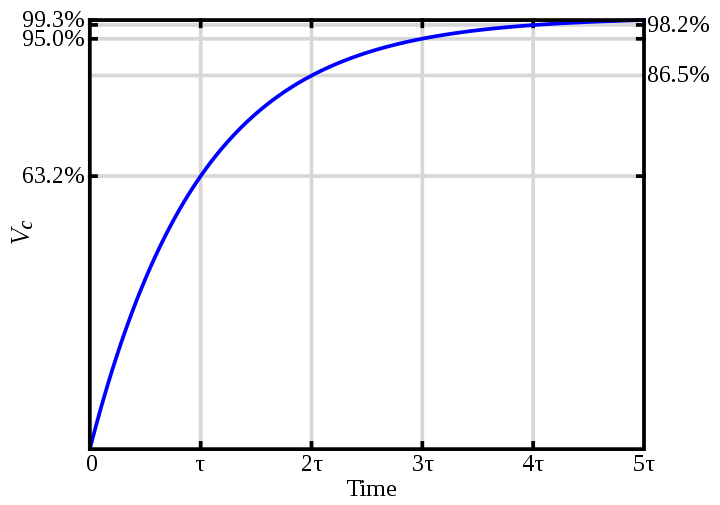
- While the capacitor is charging, current varies with time. The capacitor's charge curve slopes steeply up before leveling slowly to an asymptote; the discharge curve slopes down.
Magnetic Forces and Fields
Variables
- $F$ represents a force, measured in Newtons (vector)
- $B$ represents the magnetic field, measured in Tesla (T) (vector)
- $v$ represents velocity, measured in m/s (vector)
- $q$ represents charge, measured in Coulombs (C) (scalar)
- $L$ represents length of a bar or wire, measured in m (scalar)
- $r$ represents the radius or the radial distance from a wire, measured in m (scalar)
- $I$ represents current, measured in amps (scalar)
- $\tau$ represents torque, measured in $N \bullet m$ (vector)
- $A$ represents area, measured in $m^2$ (scalar)
- $N$ represents the number of loops in a coil (scalar)
- $t$ represents time, measured in seconds (scalar)
- $\mu_o$ represents the magnetic constant or the permeability of free space, $\mu_o = 4\pi\times10^{-7}$ Tm/A (scalar)
Equations
- $F_B = Bqv\sin{\theta}$, where $\theta$ is the angle between the velocity and the field
- 1 gauss (not SI) = $10^{-4}$ Tesla (SI)
- $W_B = \Delta KE = 0$ - no work done by B, as F is perpendicular to displacement; the force causes acceleration in direction, not speed
- $\dfrac{mv^2}{r} = Bqv \Rightarrow r = \dfrac{mv}{qB}$
- $F_B = ILB\sin{\theta}$
- $\tau = NIAB\sin{\theta}$, where $\theta$ is the angle between one arm of the loop and the magnetic field
- $B = \dfrac{\mu_oI}{2\pi r}$ for a current in a wire
Notes
- A magnetic field is formed by spinning electrons. By spinning in the same direction, they don't cancel each other out.

- In ferromagnetic materials, the atoms work in groups called domains. The domain will align with an external magnetic field. Aligned domains indicate a magnetised material.
- Each magnet has a north and a south pole; likes attract, opposites repel.
- A magnet creates a magnetic field, like an electric field. Its direction is indicated by a compass placed in the field.
- Magnetic fields lines can be drawn like those of electric fields, going from North to South.
- Moving charges placed in a magnetic field experience a force, if a component of the velocity is perpendicular to the magnetic field.
- The direction of this force can be determined with the right hand rule (RHR #1) (See figure). $\times$ represents a field into the paper, $\bullet$ out of the paper. If the moving charge is negative, the force comes out of the back of the hand.
- When entering a magnetic field perpendicularly, a charged particle will be pushed in a circular path of radius r (above).
- In a mass spectrometer, this path is used to separate particles by velocity and mass. Mass of the ions is proportional to $B^2$. Changing B allows different masses to be separated.
- Current moving through a magnetic field also experiences a force; use RHR #1 with thumb along line of current.
- A loop of wire will experience a torque in a magnetic field. The loop tends to rotate until its normal (perpendicular to loop) is parallel to field, where it will stop unless it has sufficient momentum to continue.

- Current moving through a wire produces a magnetic field. Its direction can be determined with RHR #2 (see figure). Parallel currents in the same direction attract, in opposite directions repel.
Electromagnetic Induction
Variables
- $F$ represents a force, measured in Newtons (vector)
- $B$ represents the magnetic field, measured in Tesla (T) (vector)
- $v$ represents velocity, measured in m/s (vector)
- $q$ represents charge, measured in Coulombs (C) (scalar)
- $L$ represents length of a bar or wire, measured in m (scalar)
- $I$ represents current, measured in amps (scalar)
- $A$ represents area, measured in $m^2$ (scalar)
- $N$ represents the number of loops in a coil (scalar)
- $\Phi$ represents magnetic flux, measured in Webers (Wb) (scalar)
- $\mathcal{E}$ represents the electromotive force, or emf, measured in Volts (scalar)
Equations
- $\mathcal{E} = vBL$ for a straight bar; v, B, L are mutually perpendicular
- $\phi = BA\cos{\theta}$ - uses the component of B that is perpendicular to surface
- $\mathcal{E} = -N\dfrac{\Delta\phi}{\Delta t} = -N\dfrac{\Delta AB}{\Delta t}$, or the time rate of change of flux
Notes
- Changing magnetic flux induces an emf (and therefore a current, if there is a closed circuit). This can be caused by a change in the magnetic field or in the area of a loop.
- As a bar moves through a magnetic fields, the electrons experience a force (RHR #1) which pushes them to one end, which is the negative terminal of the emf.

- For a conducting bar sliding on conducting rails, there must be a force in the direction of the velocity. Otherwise, the induced emf creates a magnetic field (and hence force) that slows the bar to a stop, where the process will repeat.
- Magnetic flux is proportional to the strength of the magnetic field passing through the plane of a loop of wire (its area).
- If given B, area, or emf, use the emf and flux equation, substituting changes in area or B; keep the constant value the same. That is, if B is constant, use $\Delta\phi = (\Delta A)B$. Change in time is usually 1 if not given.
- Lenz's Law: induced B opposes change in $\phi$. That is, if B is to the right and lessening, a B will be induced to the right, and cause a current, given by RHR #2 (put hand through centre of loop and "grab" it).
- An induced current through a loop into a circuit (by Lenz's Law) has a positive terminal where the induced current enters the external circuit.
- Often, charged particles are accelerated through a voltage difference. Use $q\mathcal{E} = \frac{1}{2}mv^2$
Electromagnetic Spectrum
Variables
- $v$ represents velocity, measured in m/s (vector)
- $\lambda$ represents wavelength, measured in metres (scalar)
- $f$ represents frequency, measured in Hz (scalar)
- $I$ represents intensity, measured in $W/m^2$ (scalar)
- $P$ represents power, measured in W (scalar)
- $A$ represents area, measured in square metres (scalar)
- $c$ represents the speed of light, $c \approx 3 \times 10^8 m/s$
- $anything_1$ represents an incident variable
- $anything_2$ represents a resultant variable
Equations
- $v = \lambda f$
- $A_{sphere} = 4 \pi r^2$
- $I = \dfrac{P}{A}$
- $I_2 = \frac{1}{2}I_1$ for polarisation
- $E_2 = E_1 \cos \theta$, where $\theta$ is the angular difference between the polariser and the analyser
- $I_2 = I_1 \cos^2 \theta$
Notes
- Maxwell showed that electric fields and magnetic fields combine to form electromagnetic waves; the fields are perpendicular to each other, and perpendicular to the direction of motion (a transverse wave). They do not need a medium to travel through, unlike sound waves.

- Electromagnetic waves are formed by an AC generator attached to two wires that serve as an antenna. As the charges change direction, an electric field in two directions is formed. The moving charges also induce a magnetic field.
- This wave is known as the near field. It decreases rapidly away from the antenna. The radiation field forms at larger distance, but with a different mechanism.
- The frequency is set by the frequency of oscillation of the electric charges, for example, the frequency of the AC generator.
- Electromagnetic waves vary widely in frequency (and therefore wavelength); see figure
- Visible light is emitted by objects that become hot enough.
- Foucault and Michelson used rotating mirrors to measure the speed of light; if the angular speed is right, the light will reflect off the spinning mirror, on to a fixed mirror, and back to the spinning mirror

- Electromagnetic waves can be polarised, due to their transverse nature; the direction of polarisation is arbitrarily determined to be the direction of the electric field
- A polariser can be used in tandem with an analyser; the angle of the analyser determines the strength of the resultant electric field, by Malus' Law
- In polarised sunglasses, the polarisation is set up so that horizontal light is blocked, as this is the prevalent light reflecting off of puddles, etc.

Reflection of Light
Variables
- $anything_1$ represents an incident variable
- $anything_2$ represents a resultant variable
- $\theta$ represents an angle with respect to the normal, measured in degrees (scalar)
- $C$ represents the centre of curvature of a spherical mirror
- $R$ represents the radius of curvature, the distance between C and the mirror, measured in metres (scalar)
- $F$ represents the focal length (or focal point) of a mirror or lens, measured in metres (scalar)
- $anything_o$ represents the object
- $anything_i$ represents the image
- $s$ represents distance, measured in metres (scalar)
- $h$ represents height, measured in metres (scalar)
- $M$ represents magnification, without units
Equations
- $\theta_1 = \theta_2$ - Law of Reflection
- $F = \frac{1}{2}R$ for paraxial rays only
- $\dfrac{1}{s_o} + \dfrac{1}{s_i} = \dfrac{1}{F}$
- $M = \dfrac{h_i}{h_o} = \dfrac{-s_i}{s_o}$
Notes
- As light waves radiate from a point source, they form spherical wave fronts. Far from the source, the curvature is so small that the wave front is essentially flat. These equations use plane wave fronts, so that the light rays are perpendicular to the front and parallel to each other.

- The angle of incidence is the angle that the incident ray makes with the normal (perpendicular) to the surface.
- When reflected from a smooth surface, rays are parallel to each other because the normals are parallel. When reflecting from a rough surface, the Law of Reflection still applies, but the normals are not parallel to each other because of variations in the surface curvature.
- The image behind a plane (flat) mirror is exactly the same as the original image. This image is called a virtual image because the rays appear to come from behind the mirror. The eye actually sees the extensions of the rays, because it can't perceive the bending of the original rays.

- An observer at an angle will see an object in a mirror at the same location as an observer at right angles to it. That is, the position of the image isn't affected by the position of the observer.
- Mirrors are often spherical, made by cutting a piece out of a sphere of glass and polishing it. They can be concave or convex.

- Rays that are close to the principal axis, or the line on which lie C and F, are called paraxial rays. Farther from the principal axis, the rays behave differently
- Spherical aberration is the inability of a spherical mirror to focus all rays to a single point; it is minimised in a mirror with a small height compared to R. Parabolic mirrors are more costly, but do focus all rays to a single point.
- Using ray diagrams can reveal where the image will be formed, but they are approximate when drawn by hand.
- Use three rays for concave mirrors:

- From tip of object, parallel to principal axis. Reflects through focal point.
- From tip of object, through focal point. Reflects parallel to principal axis.
- From tip of object, along line that passes through C. Reflects along the same line. (Because R is a radius, it is perpendicular to the surface of the mirror)
- For convex mirrors, the focal point is on the far side of the mirror. Use three rays for convex mirrors:
- From tip of object, parallel to principal axis. Appears to originate from focal point.
- From tip of object, heading towards focal point. Reflects parallel to principal axis.
- From tip of object, heading towards C. Reflects along same line.

- A virtual image is one that is formed behind the mirror; it is virtual because it is formed by the extensions of the rays, not the rays themselves.
- A real image is one that is formed in front of the mirror; it is real because it is formed by the actual rays.
- If M is negative, the image is inverted. If M is greater than 1, the image is magnified; less than 1, smaller; 1, the same size.
- Various sign conventions need to be used for the mirror equation:


| Quantity | Symbol | In front / Real | In back / virtual | Upright | Inverted |
|---|---|---|---|---|---|
| Object location | $s_o$ | + | - (multiple mirrors) | ||
| Image location | $s_i$ | + | - | ||
| Focal length | $F$ | + | - | ||
| Object height | $h_o$ | + | - | ||
| Image height | $h_i$ | + | - | ||
| Magnification | $M$ | + | - |
Chart: Summary of Images from Mirrors
Concave Mirrors
| Object location | Image location | ||
|---|---|---|---|
| Beyond C | Real | Inverted | Smaller |
| On C | Real | Inverted | Same |
| Between C and F | Real | Inverted | Larger |
| On F | no image formed | ||
| Between F and mirror | Virtual | Upright | Larger |
Convex Mirrors
| Object location | Image location | ||
|---|---|---|---|
| Anywhere near mirror | Virtual | Upright | Smaller |
Refraction of Light
Variables
- $anything_1$ represents an incident variable
- $anything_2$ represents a resultant variable
- $\theta$ represents an angle with respect to the normal, measured in degrees (scalar)
- $F$ represents the focal length (or point), measured in metres (scalar)
- $n$ represents the index of refraction, unitless
- $c$ represents the speed of light in a vacuum; $c \approx 3 \times 10^8$ m/s
- $v$ represents velocity, measured in m/s (vector)
- $f$ represents frequency, measured in Hz (scalar)
- $\lambda$ represents wavelength, measured in metres (scalar)
- $anything_o$ represents the object
- $anything_i$ represents the image
- $s$ represents distance, measured in metres (scalar)
- $h$ represents height, measured in metres (scalar)
- $M$ represents magnification, without units
- $d$ represents depth and $d'$ represents apparent depth, measured in metres (scalar)
- $N$ represents the distance to the near point of an eye, measured in metres (scalar)
Equations
- $n = \dfrac{c}{v} > 1$
- $n_1 \sin \theta_1 = n_2 \sin \theta_2$ - Snell's Law
- $d' = d\dfrac{n_2}{n_1}$
- $\lambda_{medium} = \dfrac{\lambda_{vacuum}}{n_{medium}}$
- $\sin \theta_{critical} = \dfrac{n_2}{n_1}$ for total internal reflection; only applies if $n_1 > n_2$, which the inverse sin operation will check
- $\dfrac{1}{s_o} + \dfrac{1}{s_i} = \dfrac{1}{F}$ - thin lens equation
- $M = \dfrac{h_i}{h_o} = \dfrac{-s_i}{s_o}$
- $\dfrac{1}{F} = (n-1) ( \dfrac{1}{R_1} - \dfrac{1}{R_2} )$ - lens maker's equation
Angular Magnification: $\theta$ represents the angular size of an object, measured in radians (scalar)
- $\theta = \dfrac{h_o}{s_o}$
- $M_{\theta} = \dfrac{\theta'}{\theta} \approx \dfrac{N}{s_o} \approx N( \dfrac{1}{F} - \dfrac{1}{s_i} )$
- $M_{\theta}$ varies from $\dfrac{N}{F} + 1$ when the object is at the near point to $\dfrac{N}{F}$ when the object is at infinity
- $M_{\theta} \approx - \dfrac{(L - F_e)N}{F_o F_e}$ for a compound microscope, where L is the distance between lenses and o refers to the objective and e refers to the eyepiece
- $M_{\theta} \approx -\dfrac{F_o}{F_e}$ for a refracting telescope
Notes
- Refraction occurs because light changes speed when it enters a different medium.

- The index of refraction measures how much the light will refract, or bend. Some indices of refraction:
- water: 1.33
- air: 1
- glass: 1.5
- Light incident on a surface will both reflect and refract; the amount of each depends on the angle and the intensity of the light. Due to conservation of energy, the amount of energy in the incident light equals the amount of energy in the reflected and refracted light combined.
- Unless the incident light hits along the normal ($\theta_1 = 90°$, it will be refracted.
- If going from a higher to a lower n, it is "freed", and bends away from the normal.
- If going from a lower to a higher, it is "confined", and bends towards the normal.
- When using Snell's Law, the angle must be the angle with respect to the normal, not with respect to the surface. One way to check this is by knowing beforehand whether the angle should be smaller or larger, and watching for n-values less than 1.
- If light travels through one medium immersed in another, the rays entering and leaving the medium will be parallel, but not colinear. For example, light entering a slab of glass in air is parallel to the light leaving the glass, but they enter and leave at different locations.
- When an object is immersed in a liquid, it appears closer to the surface than it actually is, due to refraction.
- When light enters a different medium, its velocity changes but frequency remains constant. Therefore, wavelength must change.

- Total internal reflection occurs when the angle of incidence is greater than the critical angle. It is caused because the refraction is so great that the light bends far enough from the normal to remain completely within the medium. This can only occur going from a high n to a low n.
- Total internal reflection is used to bend light in prisms (binoculars, etc.) and in fibre optic cable.
- Different wavelengths have different indices of refraction in various materials. This is how a prism splits light (or raindrops make rainbows) - the different wavelengths (colours) of light bend differently.
- In lenses, refraction causes the light to bend. In converging lenses, the light is bent towards the focal point. In diverging lenses, the light is scattered away from the lens; they appear to have been scattered from the focal point.
- Once again, ray diagrams can be drawn, using various rays. Unlike mirrors, lenses work in both directions, so they have two focal points.
- For converging lenses, use three rays:

- From tip of object, parallel to principal axis. Refracts through focal point on far side.
- From tip of object, through near focal point. Refracts parallel to principal axis.
- From tip of object, through centre of lens. Refracts straight through.
- For diverging lenses, use three rays:
- From tip of object, parallel to principal axis. Refracts so that it appears to be coming out of the near focal point.
- From tip of object, heading toward far focal point. Refracts parallel to principal axis.

- From tip of object, straight through centre of lens. Refracts straight through.
- When using the thin lens equation, certain sign conventions must be used:

| Symbol | In front | In back | Converging | Diverging | |
|---|---|---|---|---|---|
| Object location | $s_o$ | + | - | ||
| Image location | $s_i$ | - | + | ||
| Lens radii | $R_1, R_2$ | - | + | ||
| Focal length | $F$ | + | - |
- Magnification behaves like magnification for mirrors; - is inverse, greater than 1 is larger, less than 1 is smaller.
- If two lenses are used in combination, the one closest to the object is called the objective lens. The other is the ocular lens, or eyepiece.
- For multiple lenses, the first image serves as the object for the second lens.

- The human eye works by refracting light onto the retina. The differences in n between the air, cornea, aqueous humour, lens, and vitreous humour cause this, with most of the refraction being at the air-cornea interface. The lens changes shape to adjust the focal length. In nearsightedness, the image is focussed before contacting the retina; in farsightedness, it focuses at a point behind the retina.
- Diopters are a measure of the power of a lens. The refractive power measured in diopters is the reciprocal of the focal length, where F is measured in metres.
- Magnification can also be measured angularly, in radians.
- Refracting telescopes use lenses to form an image; due to the weight of the lens needed for a clear picture, it will sag, leading to aberrations. Hence, reflecting telescopes, using mirrors, are more often used.
- Spherical aberrations occur in lenses, because not all rays focus exactly to the same focal point. A diaphragm can be used to limit the incoming rays to the paraxial rays.
- Chromatic aberrations arise because not all colours refract the same way; they can be limited by using a compound lens that consists of a converging lens combined with a diverging lens.

Chart: Summary of Images from Lenses
Converging Lenses
| Object location | Image location | ||
|---|---|---|---|
| Beyond 2F | Real | Inverted | Smaller |
| On 2F | Real | Inverted | Same |
| Between 2F and F | Real | Inverted | Larger |
| On F | no image formed | ||
| Between F and lens | Virtual | Upright | Larger |
Diverging Lens
| Object location | Image location | ||
|---|---|---|---|
| Anywhere near lens | Virtual | Upright | Smaller |
Interference and the Wave Nature of Light
Variables
- $c$ represents the speed of light in a vacuum; $c \approx 3 \times 10^8$ m/s
- $v$ represents velocity, measured in m/s (vector)
- $f$ represents frequency, measured in Hz (scalar)
- $\lambda$ represents wavelength, measured in metres (scalar)
- $m$ represents the "order" of a fringe; dark fringes are n + 0.5, light fringes are n (unitless)
- $\theta$ represents the angle from the centre of the slit arrangement to the fringe, measured in degrees (scalar)
- $d$ represents the distance between two slits, measured in metres (scalar)
- $y$ represents the vertical distance from the centre of the slit arrangement to the fringe, measured in metres (scalar)
- $L$ represents the distance from the slit(s) to the screen, measured in metres (scalar)
- $t$ represents the thickness of a thin film, measured in metres (scalar)
- $W$ represents the width of an opening (diffraction), measured in metres (scalar)
- $\theta_{min}$ represents the minimal angle between two objects to be resolved, measured in degrees (scalar)
- $D$ represents the diameter of an optical instrument, measured in meters (scalar)
Equations
- $v = \lambda f$
- $\sin \theta = \dfrac{m \lambda}{d}$ for the double-slit experiment
- $y = \dfrac{\lambda L m}{d}$ for the double-slit experiment
- $\lambda_{film} = \dfrac{\lambda_{vacuum}}{n_{vacuum}}$
- $2t = m \lambda_{film}$ for thin film interference
- $\sin \theta = \dfrac{m\lambda}{W}$ for the minima of single-slit diffraction
- $\theta_{min} = 1.22\dfrac{\lambda}{D}$ for resolving power
Notes

- Linear superposition and interference also apply to light. A phase shift of one-half a wavelength will result in destructive interference; an integer shift results in constructive interference.
- Coherent light sources (such as lasers) emit waves in a constant wave relation. Incoherent sources (fluorescent and incandescent lights) have random con/destructive interference.
- Young's double slit experiment proved the wave nature of light, in that light waves are diffracted as other waves are. Prior to his experiment, it was believed that light was a series of particles. Now we know that it is both.
- m refers to the order of a fringe. Note that the mth dark fringe has a value of m + 0.5. For example, the third light fringe has m equal to 3, whereas the third dark fringe has m equal to 3.5 (see figure)
- Interference can also occur when a thin film of one material coats another (such as gasoline on water). Because some of the light reflects on the first surface and some refracts through the film (see figure), there's a potential for interference between the two resultant rays.

- If the light ray reflects off of a surface with a greater index of refraction, it will experience a phase shift of $\lambda / 2$. Think of it as a wave on a string: when it bounces off of a fixed end, it flips sides; when it is on a free end, it remains on the same side. Likewise, when it reflects off of a "harder" surface (higher n means more dense), it will phase shift.
- Because the ray must go through the thickness t twice, the desired change in wavelength must be equal to 2t.
- Remember that the wavelength in the film is different from that outside the film. Thus, the equation often ends up being $2t = \frac{\lambda}{n_{film}}$.
- In summary, for thin film problems:
- Mark whether the resultant rays are phase-shifted
- Decide whether destructive or constructive interference is described by the problem
- Set up $2t = m\frac{\lambda}{n}$ or $2t = (m+\frac{1}{2})\frac{\lambda}{n}$, depending on the result of step 2

- Using m = {0,1,2…} gives the possible answers. (Interference can be caused by any multiple of the wavelength, hence the need to multiple by m)
- The Michelson interferometer measures the wavelength of light based on the difference between two light waves. By altering the distance they travel and observing when constructive and destructive interference occurs, one can determine one-half multiples of the wavelength.
- Diffraction is the result of interference of waves. It is caused by waves bending around obstacles or through an opening. The diffraction of light is to a very small degree - for example, we can hear around corners, but we can't see around corners.
- Huygen's Principle states that every point on a wave front acts as a source of tiny wavelets that move forward with the same speed as the wave; the wave front at a later moment is the surface tangent to these wavelets.

- In double-slit diffraction, the pattern produced light and dark fringes of roughly the same intensity. In single-slit diffraction, the central fringe is the brightest, and the other fringes rapidly diminish in intensity (see figure).
- The amount of diffraction is proportional to $\frac{\lambda}{W}$. The width of the central maximum is also larger if there's more diffraction, or a smaller slit. (Decreasing W increases the fraction, so a larger angle means the central maximum reaches farther).

- For single slit diffraction, the equation gives the angles to the minima, or dark fringes. The maxima, or bright fringes, are located between the dark fringes, so their widths can be determined by subtracting the locations of the dark fringes.
- Resolving power refers to the ability of an optical instrument to distinguish between two closely spaced objects. That is, will two dots look like two dots (well resolved, c), a wide dot (barely resolved, b), or one dot (not resolved, a)?
- Rayleigh's criteria for resolving power states that two objects are resolved when the first dark fringe of one falls directly on the central bright fringe of the other.
- For the minimum angle to be resolved, smaller is better (closer objects can be more clearly resolved). This angle's vertex is the centre of the instrument's opening, and the two objects form the endpoints of the angle's rays.
- Diffraction gratings have a large number of equally spaced parallel slits (as many as 40,000 slits per cm). They diffract using the same formula as for single-slit diffraction, but d is the reciprocal of the number of slits per cm. Also, secondary fringes occur between the primary fringes, but they are very small in intensity for gratings with large numbers of slits.
- Diffraction gratings can separate colours, as well. Sunlight will produce a rainbow at each principal maximum.


Modern Physics
Variables
Equations
Notes
Image sources can be found under "files", "info" below.